ES2 filters in Logic Pro for iPad
ES2 features two discrete, and different, filters.
Filter 1 is a multimode filter (MMF) that can operate as a lowpass, highpass, bandpass, band reject, or peak filter.
Filter 2 is a lowpass filter (LPF) that offers variable slopes (measured in dB/octave).
Dual Filter Global parameters
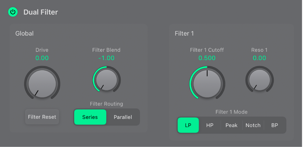
On/Off button: Turn the entire filter section on or off. Deactivating the filter section makes it easier to hear adjustments to other sound parameters, because the filters always heavily affect the sound. Disabling the filters also reduces processor load.
Drive knob and field: Rotate to overdrive the filter, which affects each voice independently. See Overdrive ES2 filters.
 Filter Blend knob and field: Set the balance between Filter 1 and Filter 2. See Crossfade between ES2 filters.
Filter Reset button: Turn on Filter Reset to provide a trigger signal that can be used to drive the filter to self-oscillate. See Filter cutoff and resonance.
Filter Routing buttons: Switch between a parallel or series filter configuration.
Series: This means that the signal of all oscillators (combined at the Oscillator Mix pad) passes through the first filter, then this filtered signal passes through Filter 2, if Filter Blend is set to 0, the middle position. The output signal of Filter 2 is then sent to the input of the dynamic stage (Amplifier section).
Parallel: If Filter Blend is set to 0, you’ll hear a 50/50 mix of the source signal, routed via Filter 1 and Filter 2. The output signals of the two filters are then sent to the input of the dynamic stage. See Crossfade between ES2 filters.
Filter 1 and Filter 2 parameters
- Filter 1 Cutoff knob and field: Set the cutoff frequency of the multimode filter (Filter 1). See Filter cutoff and resonance.
Reso 1 knob and field: Determine the resonance behavior of the multimode filter (Filter 1).
Filter 1 Mode buttons: Switch Filter 1 between lowpass (LP), highpass (HP), bandpass (BP), band reject (Notch), or peak filter types.
LP: Allow frequencies that fall below the cutoff frequency to pass. The slope of Filter 1 is fixed at 12 dB/octave.
HP: Allow frequencies above the cutoff frequency to pass. The slope of Filter 1 is fixed at 12 dB/octave.
Peak: Filter 1 works as a peak filter. This allows the level in a frequency band to be increased. The center of the frequency band is determined by the Cutoff parameter. The width of the band is controlled by the Resonance parameter.
Notch: The frequency band directly surrounding the cutoff frequency is rejected, but frequencies outside this band can pass. The Resonance parameter controls the width of the rejected frequency band.
BP: The frequency band directly surrounding the cutoff frequency is allowed to pass. All other frequencies are cut. The Resonance parameter controls the width of the frequency band. The bandpass filter is a two-pole filter with a slope of 6 dB/octave on each side of the center frequency.
- Filter 2 Cutoff knob and field: Set the cutoff frequency of the low pass filter (Filter 2). See Filter cutoff and resonance.
Reso 2 knob and field: Determine the resonance behavior of the low pass filter (Filter 2).
Filter 2 FM knob and field: Set the amount of Filter 2 cutoff frequency modulation with the oscillator 1 frequency. See Modulate ES2 Filter 2 frequency.
Filter 2 Fatness button: Adds 24 dB per octave of rejection. Fat mode has a built-in compensation circuit that retains the sound bottom end. By comparison, the standard 24 dB mode tends to make lower end sounds less rich.
Filter 2 Mode buttons: Choose a Filter 2 slope: 12 dB, 18 dB, and 24 dB. The steeper the slope, the more severe the effect on signal levels below the cutoff frequency. Most filters do not completely suppress the portion of the signal that falls outside the frequency range defined by the Cutoff parameter. The slope, or curve, chosen for Filter 2 expresses the amount of rejection below the cutoff frequency in decibels per octave.
Download this guide: PDF