> For the complete documentation index, see [llms.txt](https://pcgex.gitbook.io/pcgex/llms.txt). Markdown versions of documentation pages are available by appending `.md` to page URLs; this page is available as [Markdown](https://pcgex.gitbook.io/pcgex/zone-graph/pcgex-+-zonegraph.md).

# PCGEx + ZoneGraph

One PCG node that reads a PCGEx cluster and builds Unreal's Zone Graph from it: roads, intersections, lane profiles and the lot, without hand-placing a single zone shape.

A cluster already says which points connect to which. That is most of what a Zone Graph needs, in the wrong shape. **Cluster to Zone Graph** reads that connectivity and builds the shapes, already joined to each other, so whatever produced your road network, it arrives as a lane network vehicles and crowds can use.

{% hint style="success" %}
Epic's [Zone Graph Quick Start Guide](https://dev.epicgames.com/community/learning/tutorials/qz6r/unreal-engine-zonegraph-quick-start-guide) is the short way in if lane profiles and zone shapes are new. This book teaches the bridge and links out for either side of it.
{% endhint %}

## What comes out

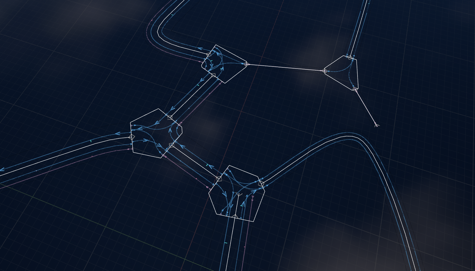
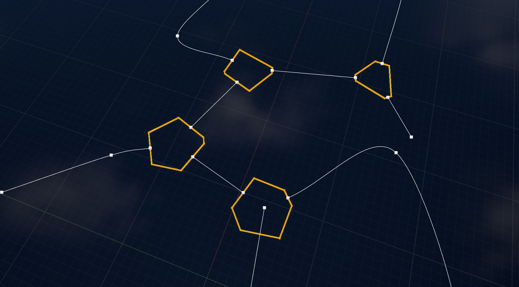
*Two kinds of zone shape, and the cluster's own connectivity decides which goes where.*

Vertices where three or more edges meet become polygon intersections. The chains of edges between them become spline roads. Leaf vertices are where a road stops. Nothing needs placing by hand, and one node covers a network of any size.

<figure><img src="https://934896435-files.gitbook.io/~/files/v0/b/gitbook-x-prod.appspot.com/o/spaces%2F2P5K980GR54iC167OVeC%2Fuploads%2FebhRLksAbyKBjvCgvtzJ%2Fimage.png?alt=media&amp;token=2f8d82e0-e0b3-4e7d-a5c8-c79e7cd2ad6d" alt="STILL | id: readme-grid-network | SHOWS: the same node applied to an orthogonal street grid, so a reader sees the decomposition is topological rather than tuned to one network shape | FRAME: near top-down viewport over an orthogonal grid network with ZoneGraph lane debug drawing enabled, showing a polygon at every crossing and lanes routed through each of them | SOURCE: a grid cluster run through the node at default settings"><figcaption><p>The same rule, on a grid: a polygon at every crossing, with lanes routed through each.</p></figcaption></figure>

The same rule handles a regular grid, where every crossing is a junction and the intersection count climbs fast.

<div><figure><img src="https://934896435-files.gitbook.io/~/files/v0/b/gitbook-x-prod.appspot.com/o/spaces%2F2P5K980GR54iC167OVeC%2Fuploads%2FNtlJeWppamFKfrIVrbVY%2Fimage.png?alt=media&amp;token=392697dc-a4f2-4d19-8d23-c4cfb89a9e4d" alt="STILL | id: readme-generated-network | SHOWS: a branching road network produced by the node, with intersections and lane directions resolved across the whole thing | FRAME: angled viewport over an organic branching network with ZoneGraph lane debug drawing enabled, showing lane centerlines with direction arrows, lane boundaries, and white polygon outlines at the junctions | SOURCE: a hand-authored organic cluster run through the node at default settings"><figcaption></figcaption></figure> <figure><img src="https://934896435-files.gitbook.io/~/files/v0/b/gitbook-x-prod.appspot.com/o/spaces%2F2P5K980GR54iC167OVeC%2Fuploads%2FwV4I9KtD0z2s2GjoLuLX%2FOutputs.gif?alt=media&amp;token=59958ae1-74f8-4b3a-a712-4c8d95e57519" alt=""><figcaption><p>Every junction became a polygon, every run between them a road, and lane direction resolved across the network in one pass.</p></figcaption></figure></div>

## Connections that land by construction

*Zone Graph joins two shapes when four separate things agree about them. The node arranges all four rather than approaching them.*

Building a lane network by hand is mostly positioning. A road joins an intersection only when its end connector and the intersection's arm carry the same lane profile, sit inside the project's connection snap distance, face each other inside the snap angle, and read that profile in opposite directions. Miss one of the four and the two shapes do not connect: the editor draws that connector grey instead of white, lanes stop dead at the junction, and working out which of the four went wrong is yours to do, per connector, across the network.

| What Zone Graph tests                      | How the node satisfies it                                                            |
| ------------------------------------------ | ------------------------------------------------------------------------------------ |
| Both sides carry the same lane profile     | The intersection's arm is handed the profile its road resolved                       |
| The two are within snap distance           | Both positions come out of one expression, so the distance is zero rather than small |
| They face each other within the snap angle | The arm faces back down its road, so the two normals are exactly opposed             |
| The profile reads in opposite directions   | The road carries the flip and the arm carries its opposite, by construction          |

Nothing is nudged toward a tolerance, because nothing is approaching one. A road does not arrive near its intersection; it terminates on the point the intersection put there.

That matters most after the first build. Move a spline, repaint a lane profile, insert a junction, regenerate, and every connection in the network is derived again from the topology that changed. Control points placed by hand stay where they were put.

## Where the connectivity comes from

*The node reads a cluster, and has no opinion about what produced it.*

A cluster is points and the connections between them, and PCGEx will build one out of most things a PCG graph can reach.

| If you already have                                    | Build the cluster with                                                                                                                                 |
| ------------------------------------------------------ | ------------------------------------------------------------------------------------------------------------------------------------------------------ |
| Splines laid out in the level                          | [Path : To Clusters](https://pcgex.gitbook.io/pcgex/node-library/clusters/interop/path-to-clusters), which fuses their crossings into shared junctions |
| Points from anywhere, to be wired by a rule you choose | [Cluster : Connect Points](https://pcgex.gitbook.io/pcgex/node-library/clusters/generate/cluster-connect-points)                                       |
| Points you want triangulated                           | [Cluster : Delaunay 2D](https://pcgex.gitbook.io/pcgex/node-library/clusters/generate/cluster-delaunay-2d)                                             |
| A mesh whose topology is the network                   | [Mesh to Clusters](https://pcgex.gitbook.io/pcgex/node-library/clusters/generate/mesh-to-clusters)                                                     |

Whatever produced them, this node sees the same two datasets. A road network an artist drew by hand and one a graph invented from noise take the identical route from here, so there is no ZoneGraph-specific authoring path to keep alongside the one you already have. Swapping a hand-authored source for a generated one, or the reverse, changes nothing downstream of the cluster.

## Intersections that match the roads meeting them

*Each connection point carries the lane profile of its own road, so a junction can mix them.*

A road resolves its lane profile from an attribute on its edges, and every connection point on the intersection it reaches inherits that profile. A four-lane arterial and a single-lane alley can meet at the same polygon and Zone Graph routes between them without any manual pairing.

Intersections can also size themselves from those profiles rather than from a number you picked, so a wide road produces a wide footprint and a narrow one does not.

<div><figure><img src="https://934896435-files.gitbook.io/~/files/v0/b/gitbook-x-prod.appspot.com/o/spaces%2F2P5K980GR54iC167OVeC%2Fuploads%2F30sYfeLz2DNJOTRjuTFy%2Fimage.png?alt=media&amp;token=b40b4af3-7cc2-4753-a8a0-676673bdce95" alt="STILL | id: readme-profiles-meeting | SHOWS: roads of different lane profiles meeting at shared intersections, with lanes routed across each polygon | FRAME: angled viewport over a junction cluster with ZoneGraph lane debug drawing enabled, framed so that roads of visibly different lane counts arrive at the same polygons and the routed lanes crossing each polygon interior are legible | SOURCE: a cluster carrying a per-edge lane profile attribute with at least two distinct profiles"><figcaption></figcaption></figure> <figure><img src="https://934896435-files.gitbook.io/~/files/v0/b/gitbook-x-prod.appspot.com/o/spaces%2F2P5K980GR54iC167OVeC%2Fuploads%2Fkr4jxWxPVAnCBL5R92Q9%2FRotato.gif?alt=media&amp;token=156586b2-49c5-44ed-bb3f-7767a5879036" alt=""><figcaption><p>Different profiles arriving at one intersection, with lanes routed across its interior between them.</p></figcaption></figure></div>

## What you steer

*Where intersections appear, how large they are, which way lanes run, and what each road carries.*

The default decomposition needs nothing configured. Past that, filters put an intersection anywhere you want one, radii can be derived from lane widths or authored per vertex, orientation is resolved network-wide from the shape of the graph, a merge pass fuses intersections that should have been one, and almost every value on the node reads from a point attribute if you would rather drive it from data.

{% content-ref url="/pages/gNs6tq40F74bp5vwsbsq" %}
[Overview](/pcgex/zone-graph/working-with-zonegraph/overview.md)
{% endcontent-ref %}

## Geometry back out as PCG data

*Two optional pins hand the generated shapes back as paths.*

Roads come back as open paths carrying their tangents, intersections as closed paths tracing their boundaries. Useful for spawning road furniture along a lane, or for keeping clutter off a junction.

<figure><img src="https://934896435-files.gitbook.io/~/files/v0/b/gitbook-x-prod.appspot.com/o/spaces%2F2P5K980GR54iC167OVeC%2Fuploads%2FHLIGKfkehKtV6pX4ppIF%2Fimage.png?alt=media&amp;token=110e18c0-7fd0-4a4c-91a1-2737716d225e" alt="STILL | id: readme-path-outputs | SHOWS: what the two optional path pins emit, as PCG data rather than as zone shapes | FRAME: angled viewport over a small network showing road paths as open point runs following each road and polygon paths as closed loops around each intersection, with the individual path points visible | SOURCE: the same cluster as the network still, with Output Polygon Paths and Output Road Paths both enabled"><figcaption><p>Closed loops around each intersection, open runs along each road, both as ordinary PCG paths.</p></figcaption></figure>

## Getting it

The plugin is a Pro extension, and installing the PCGEx Pro bundle is the whole install. [Installation](/pcgex/zone-graph/getting-started/installation.md) covers that, the source route for trial and source-access holders, and what your project needs enabled first; [Quick Setup](/pcgex/zone-graph/getting-started/quick-setup.md) gets a first graph running once it is in.


---

# Agent Instructions
This documentation is published with GitBook. GitBook is the documentation platform designed so that both humans and AI agents can read, navigate, and reason over technical content effectively. Learn more at gitbook.com.

## Querying This Documentation
If you need additional information that is not directly available in this page, you can query the documentation dynamically by asking a question.

Perform an HTTP GET request on the current page URL with the `ask` query parameter, and the optional `goal` query parameter:

```
GET https://pcgex.gitbook.io/pcgex/zone-graph/pcgex-+-zonegraph.md?ask=<question>&goal=<endgoal>
```

`ask` is the immediate question: it should be specific, self-contained, and written in natural language.
`goal` is optional and describes the broader end goal you are ultimately trying to accomplish on behalf of the user. GitBook uses it to tailor the answer towards what is most useful for that goal.

The response will contain a direct answer to the question and relevant excerpts and sources from the documentation.

Use this mechanism when the answer is not explicitly present in the current page, you need clarification or additional context, or you want to retrieve related documentation sections.